Lessons In Electric Circuits -- Volume I (DC) - Chapter 8
Previous> Contents
 Next
Next
Lessons In Electric Circuits -- Volume I
Chapter 8
DC METERING CIRCUITS
- What is a meter?
- Voltmeter design
- Voltmeter impact on measured circuit
- Ammeter design
- Ammeter impact on measured circuit
- Ohmmeter design
- High voltage ohmmeters
- Multimeters
- Kelvin (4-wire) resistance measurement
- Bridge circuits
- Wattmeter design
- Creating custom calibration resistances
- Contributors
What is a meter?
A meter is any device built to accurately detect and display an electrical quantity in a form readable by a human being. Usually this "readable form" is visual: motion of a pointer on a scale, a series of lights arranged to form a "bargraph," or some sort of display composed of numerical figures. In the analysis and testing of circuits, there are meters designed to accurately measure the basic quantities of voltage, current, and resistance. There are many other types of meters as well, but this chapter primarily covers the design and operation of the basic three.
Most modern meters are "digital" in design, meaning that their readable display is in the form of numerical digits. Older designs of meters are mechanical in nature, using some kind of pointer device to show quantity of measurement. In either case, the principles applied in adapting a display unit to the measurement of (relatively) large quantities of voltage, current, or resistance are the same.
The display mechanism of a meter is often referred to as a movement, borrowing from its mechanical nature to move a pointer along a scale so that a measured value may be read. Though modern digital meters have no moving parts, the term "movement" may be applied to the same basic device performing the display function.
The design of digital "movements" is beyond the scope of this chapter, but mechanical meter movement designs are very understandable. Most mechanical movements are based on the principle of electromagnetism: that electric current through a conductor produces a magnetic field perpendicular to the axis of electron flow. The greater the electric current, the stronger the magnetic field produced. If the magnetic field formed by the conductor is allowed to interact with another magnetic field, a physical force will be generated between the two sources of fields. If one of these sources is free to move with respect to the other, it will do so as current is conducted through the wire, the motion (usually against the resistance of a spring) being proportional to strength of current.
The first meter movements built were known as galvanometers, and were usually designed with maximum sensitivity in mind. A very simple galvanometer may be made from a magnetized needle (such as the needle from a magnetic compass) suspended from a string, and positioned within a coil of wire. Current through the wire coil will produce a magnetic field which will deflect the needle from pointing in the direction of earth's magnetic field. An antique string galvanometer is shown in the following photograph:

Such instruments were useful in their time, but have little place in the modern world except as proof-of-concept and elementary experimental devices. They are highly susceptible to motion of any kind, and to any disturbances in the natural magnetic field of the earth. Now, the term "galvanometer" usually refers to any design of electromagnetic meter movement built for exceptional sensitivity, and not necessarily a crude device such as that shown in the photograph. Practical electromagnetic meter movements can be made now where a pivoting wire coil is suspended in a strong magnetic field, shielded from the majority of outside influences. Such an instrument design is generally known as a permanent-magnet, moving coil, or PMMC movement:
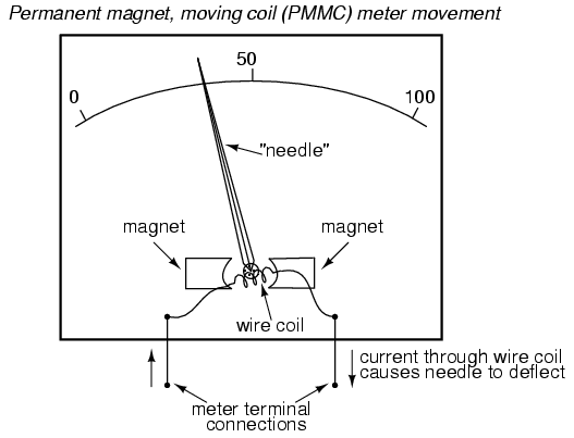
In the picture above, the meter movement "needle" is shown pointing somewhere around 35 percent of full-scale, zero being full to the left of the arc and full-scale being completely to the right of the arc. An increase in measured current will drive the needle to point further to the right and a decrease will cause the needle to drop back down toward its resting point on the left. The arc on the meter display is labeled with numbers to indicate the value of the quantity being measured, whatever that quantity is. In other words, if it takes 50 microamps of current to drive the needle fully to the right (making this a "50 µA full-scale movement"), the scale would have 0 µA written at the very left end and 50 µA at the very right, 25 µA being marked in the middle of the scale. In all likelihood, the scale would be divided into much smaller graduating marks, probably every 5 or 1 µA, to allow whoever is viewing the movement to infer a more precise reading from the needle's position.
The meter movement will have a pair of metal connection terminals on the back for current to enter and exit. Most meter movements are polarity-sensitive, one direction of current driving the needle to the right and the other driving it to the left. Some meter movements have a needle that is spring-centered in the middle of the scale sweep instead of to the left, thus enabling measurements of either polarity:

Common polarity-sensitive movements include the D'Arsonval and Weston designs, both PMMC-type instruments. Current in one direction through the wire will produce a clockwise torque on the needle mechanism, while current the other direction will produce a counter-clockwise torque.
Some meter movements are polarity-insensitive, relying on the attraction of an unmagnetized, movable iron vane toward a stationary, current-carrying wire to deflect the needle. Such meters are ideally suited for the measurement of alternating current (AC). A polarity-sensitive movement would just vibrate back and forth uselessly if connected to a source of AC.
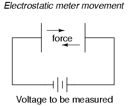
While most mechanical meter movements are based on electromagnetism (electron flow through a conductor creating a perpendicular magnetic field), a few are based on electrostatics: that is, the attractive or repulsive force generated by electric charges across space. This is the same phenomenon exhibited by certain materials (such as wax and wool) when rubbed together. If a voltage is applied between two conductive surfaces across an air gap, there will be a physical force attracting the two surfaces together capable of moving some kind of indicating mechanism. That physical force is directly proportional to the voltage applied between the plates, and inversely proportional to the square of the distance between the plates. The force is also irrespective of polarity, making this a polarity-insensitive type of meter movement:
Unfortunately, the force generated by the electrostatic attraction is very small for common voltages. In fact, it is so small that such meter movement designs are impractical for use in general test instruments. Typically, electrostatic meter movements are used for measuring very high voltages (many thousands of volts). One great advantage of the electrostatic meter movement, however, is the fact that it has extremely high resistance, whereas electromagnetic movements (which depend on the flow of electrons through wire to generate a magnetic field) are much lower in resistance. As we will see in greater detail to come, greater resistance (resulting in less current drawn from the circuit under test) makes for a better voltmeter.
A much more common application of electrostatic voltage measurement is seen in an device known as a Cathode Ray Tube, or CRT. These are special glass tubes, very similar to television viewscreen tubes. In the cathode ray tube, a beam of electrons traveling in a vacuum are deflected from their course by voltage between pairs of metal plates on either side of the beam. Because electrons are negatively charged, they tend to be repelled by the negative plate and attracted to the positive plate. A reversal of voltage polarity across the two plates will result in a deflection of the electron beam in the opposite direction, making this type of meter "movement" polarity-sensitive:
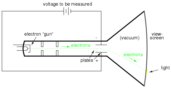
The electrons, having much less mass than metal plates, are moved by this electrostatic force very quickly and readily. Their deflected path can be traced as the electrons impinge on the glass end of the tube where they strike a coating of phosphorus chemical, emitting a glow of light seen outside of the tube. The greater the voltage between the deflection plates, the further the electron beam will be "bent" from its straight path, and the further the glowing spot will be seen from center on the end of the tube.
A photograph of a CRT is shown here:
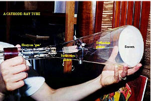
In a real CRT, as shown in the above photograph, there are two pairs of deflection plates rather than just one. In order to be able to sweep the electron beam around the whole area of the screen rather than just in a straight line, the beam must be deflected in more than one dimension.
Although these tubes are able to accurately register small voltages, they are bulky and require electrical power to operate (unlike electromagnetic meter movements, which are more compact and actuated by the power of the measured signal current going through them). They are also much more fragile than other types of electrical metering devices. Usually, cathode ray tubes are used in conjunction with precise external circuits to form a larger piece of test equipment known as an oscilloscope, which has the ability to display a graph of voltage over time, a tremendously useful tool for certain types of circuits where voltage and/or current levels are dynamically changing.
Whatever the type of meter or size of meter movement, there will be a rated value of voltage or current necessary to give full-scale indication. In electromagnetic movements, this will be the "full-scale deflection current" necessary to rotate the needle so that it points to the exact end of the indicating scale. In electrostatic movements, the full-scale rating will be expressed as the value of voltage resulting in the maximum deflection of the needle actuated by the plates, or the value of voltage in a cathode-ray tube which deflects the electron beam to the edge of the indicating screen. In digital "movements," it is the amount of voltage resulting in a "full-count" indication on the numerical display: when the digits cannot display a larger quantity.
The task of the meter designer is to take a given meter movement and design the necessary external circuitry for full-scale indication at some specified amount of voltage or current. Most meter movements (electrostatic movements excepted) are quite sensitive, giving full-scale indication at only a small fraction of a volt or an amp. This is impractical for most tasks of voltage and current measurement. What the technician often requires is a meter capable of measuring high voltages and currents.
By making the sensitive meter movement part of a voltage or current divider circuit, the movement's useful measurement range may be extended to measure far greater levels than what could be indicated by the movement alone. Precision resistors are used to create the divider circuits necessary to divide voltage or current appropriately. One of the lessons you will learn in this chapter is how to design these divider circuits.
- REVIEW:
- A "movement" is the display mechanism of a meter.
- Electromagnetic movements work on the principle of a magnetic field being generated by electric current through a wire. Examples of electromagnetic meter movements include the D'Arsonval, Weston, and iron-vane designs.
- Electrostatic movements work on the principle of physical force generated by an electric field between two plates.
- Cathode Ray Tubes (CRT's) use an electrostatic field to bend the path of an electron beam, providing indication of the beam's position by light created when the beam strikes the end of the glass tube.
Voltmeter design
As was stated earlier, most meter movements are sensitive devices. Some D'Arsonval movements have full-scale deflection current ratings as little as 50 µA, with an (internal) wire resistance of less than 1000 Ω. This makes for a voltmeter with a full-scale rating of only 50 millivolts (50 µA X 1000 Ω)! In order to build voltmeters with practical (higher voltage) scales from such sensitive movements, we need to find some way to reduce the measured quantity of voltage down to a level the movement can handle.
Let's start our example problems with a D'Arsonval meter movement having a full-scale deflection rating of 1 mA and a coil resistance of 500 Ω:

Using Ohm's Law (E=IR), we can determine how much voltage will drive this meter movement directly to full scale:
E = I R
E = (1 mA)(500 Ω)
E = 0.5 volts
If all we wanted was a meter that could measure 1/2 of a volt, the bare meter movement we have here would suffice. But to measure greater levels of voltage, something more is needed. To get an effective voltmeter meter range in excess of 1/2 volt, we'll need to design a circuit allowing only a precise proportion of measured voltage to drop across the meter movement. This will extend the meter movement's range to being able to measure higher voltages than before. Correspondingly, we will need to re-label the scale on the meter face to indicate its new measurement range with this proportioning circuit connected.
But how do we create the necessary proportioning circuit? Well, if our intention is to allow this meter movement to measure a greater voltage than it does now, what we need is a voltage divider circuit to proportion the total measured voltage into a lesser fraction across the meter movement's connection points. Knowing that voltage divider circuits are built from series resistances, we'll connect a resistor in series with the meter movement (using the movement's own internal resistance as the second resistance in the divider):

The series resistor is called a "multiplier" resistor because it multiplies the working range of the meter movement as it proportionately divides the measured voltage across it. Determining the required multiplier resistance value is an easy task if you're familiar with series circuit analysis.
For example, let's determine the necessary multiplier value to make this 1 mA, 500 Ω movement read exactly full-scale at an applied voltage of 10 volts. To do this, we first need to set up an E/I/R table for the two series components:
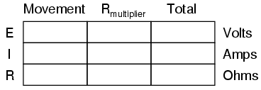
Knowing that the movement will be at full-scale with 1 mA of current going through it, and that we want this to happen at an applied (total series circuit) voltage of 10 volts, we can fill in the table as such:

There are a couple of ways to determine the resistance value of the multiplier. One way is to determine total circuit resistance using Ohm's Law in the "total" column (R=E/I), then subtract the 500 Ω of the movement to arrive at the value for the multiplier:
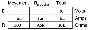
Another way to figure the same value of resistance would be to determine voltage drop across the movement at full-scale deflection (E=IR), then subtract that voltage drop from the total to arrive at the voltage across the multiplier resistor. Finally, Ohm's Law could be used again to determine resistance (R=E/I) for the multiplier:

Either way provides the same answer (9.5 kΩ), and one method could be used as verification for the other, to check accuracy of work.

With exactly 10 volts applied between the meter test leads (from some battery or precision power supply), there will be exactly 1 mA of current through the meter movement, as restricted by the "multiplier" resistor and the movement's own internal resistance. Exactly 1/2 volt will be dropped across the resistance of the movement's wire coil, and the needle will be pointing precisely at full-scale. Having re-labeled the scale to read from 0 to 10 V (instead of 0 to 1 mA), anyone viewing the scale will interpret its indication as ten volts. Please take note that the meter user does not have to be aware at all that the movement itself is actually measuring just a fraction of that ten volts from the external source. All that matters to the user is that the circuit as a whole functions to accurately display the total, applied voltage.
This is how practical electrical meters are designed and used: a sensitive meter movement is built to operate with as little voltage and current as possible for maximum sensitivity, then it is "fooled" by some sort of divider circuit built of precision resistors so that it indicates full-scale when a much larger voltage or current is impressed on the circuit as a whole. We have examined the design of a simple voltmeter here. Ammeters follow the same general rule, except that parallel-connected "shunt" resistors are used to create a current divider circuit as opposed to the series-connected voltage divider "multiplier" resistors used for voltmeter designs.
Generally, it is useful to have multiple ranges established for an electromechanical meter such as this, allowing it to read a broad range of voltages with a single movement mechanism. This is accomplished through the use of a multi-pole switch and several multiplier resistors, each one sized for a particular voltage range:

The five-position switch makes contact with only one resistor at a time. In the bottom (full clockwise) position, it makes contact with no resistor at all, providing an "off" setting. Each resistor is sized to provide a particular full-scale range for the voltmeter, all based on the particular rating of the meter movement (1 mA, 500 Ω). The end result is a voltmeter with four different full-scale ranges of measurement. Of course, in order to make this work sensibly, the meter movement's scale must be equipped with labels appropriate for each range.
With such a meter design, each resistor value is determined by the same technique, using a known total voltage, movement full-scale deflection rating, and movement resistance. For a voltmeter with ranges of 1 volt, 10 volts, 100 volts, and 1000 volts, the multiplier resistances would be as follows:

Note the multiplier resistor values used for these ranges, and how odd they are. It is highly unlikely that a 999.5 kΩ precision resistor will ever be found in a parts bin, so voltmeter designers often opt for a variation of the above design which uses more common resistor values:

With each successively higher voltage range, more multiplier resistors are pressed into service by the selector switch, making their series resistances add for the necessary total. For example, with the range selector switch set to the 1000 volt position, we need a total multiplier resistance value of 999.5 kΩ. With this meter design, that's exactly what we'll get:
RTotal = R4 + R3 + R2 + R1
RTotal = 900 kΩ + 90 kΩ + 9 kΩ + 500 Ω
RTotal = 999.5 kΩ
The advantage, of course, is that the individual multiplier resistor values are more common (900k, 90k, 9k) than some of the odd values in the first design (999.5k, 99.5k, 9.5k). From the perspective of the meter user, however, there will be no discernible difference in function.
- REVIEW:
- Extended voltmeter ranges are created for sensitive meter movements by adding series "multiplier" resistors to the movement circuit, providing a precise voltage division ratio.
Voltmeter impact on measured circuit
Every meter impacts the circuit it is measuring to some extent, just as any tire-pressure gauge changes the measured tire pressure slightly as some air is let out to operate the gauge. While some impact is inevitable, it can be minimized through good meter design.
Since voltmeters are always connected in parallel with the component or components under test, any current through the voltmeter will contribute to the overall current in the tested circuit, potentially affecting the voltage being measured. A perfect voltmeter has infinite resistance, so that it draws no current from the circuit under test. However, perfect voltmeters only exist in the pages of textbooks, not in real life! Take the following voltage divider circuit as an extreme example of how a realistic voltmeter might impact the circuit it's measuring:
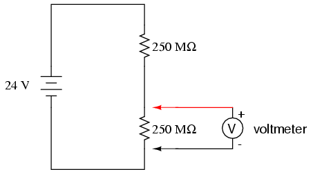
With no voltmeter connected to the circuit, there should be exactly 12 volts across each 250 MΩ resistor in the series circuit, the two equal-value resistors dividing the total voltage (24 volts) exactly in half. However, if the voltmeter in question has a lead-to-lead resistance of 10 MΩ (a common amount for a modern digital voltmeter), its resistance will create a parallel subcircuit with the lower resistor of the divider when connected:

This effectively reduces the lower resistance from 250 MΩ to 9.615 MΩ (250 MΩ and 10 MΩ in parallel), drastically altering voltage drops in the circuit. The lower resistor will now have far less voltage across it than before, and the upper resistor far more.
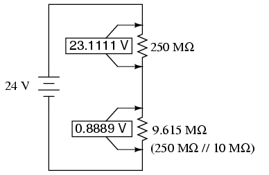
A voltage divider with resistance values of 250 MΩ and 9.615 MΩ will divide 24 volts into portions of 23.1111 volts and 0.8889 volts, respectively. Since the voltmeter is part of that 9.615 MΩ resistance, that is what it will indicate: 0.8889 volts.
Now, the voltmeter can only indicate the voltage it's connected across. It has no way of "knowing" there was a potential of 12 volts dropped across the lower 250 MΩ resistor before it was connected across it. The very act of connecting the voltmeter to the circuit makes it part of the circuit, and the voltmeter's own resistance alters the resistance ratio of the voltage divider circuit, consequently affecting the voltage being measured.
Imagine using a tire pressure gauge that took so great a volume of air to operate that it would deflate any tire it was connected to. The amount of air consumed by the pressure gauge in the act of measurement is analogous to the current taken by the voltmeter movement to move the needle. The less air a pressure gauge requires to operate, the less it will deflate the tire under test. The less current drawn by a voltmeter to actuate the needle, the less it will burden the circuit under test.
This effect is called loading, and it is present to some degree in every instance of voltmeter usage. The scenario shown here is worst-case, with a voltmeter resistance substantially lower than the resistances of the divider resistors. But there always will be some degree of loading, causing the meter to indicate less than the true voltage with no meter connected. Obviously, the higher the voltmeter resistance, the less loading of the circuit under test, and that is why an ideal voltmeter has infinite internal resistance.
Voltmeters with electromechanical movements are typically given ratings in "ohms per volt" of range to designate the amount of circuit impact created by the current draw of the movement. Because such meters rely on different values of multiplier resistors to give different measurement ranges, their lead-to-lead resistances will change depending on what range they're set to. Digital voltmeters, on the other hand, often exhibit a constant resistance across their test leads regardless of range setting (but not always!), and as such are usually rated simply in ohms of input resistance, rather than "ohms per volt" sensitivity.
What "ohms per volt" means is how many ohms of lead-to-lead resistance for every volt of range setting on the selector switch. Let's take our example voltmeter from the last section as an example:
On the 1000 volt scale, the total resistance is 1 MΩ (999.5 kΩ + 500Ω), giving 1,000,000 Ω per 1000 volts of range, or 1000 ohms per volt (1 kΩ/V). This ohms-per-volt "sensitivity" rating remains constant for any range of this meter:

The astute observer will notice that the ohms-per-volt rating of any meter is determined by a single factor: the full-scale current of the movement, in this case 1 mA. "Ohms per volt" is the mathematical reciprocal of "volts per ohm," which is defined by Ohm's Law as current (I=E/R). Consequently, the full-scale current of the movement dictates the Ω/volt sensitivity of the meter, regardless of what ranges the designer equips it with through multiplier resistors. In this case, the meter movement's full-scale current rating of 1 mA gives it a voltmeter sensitivity of 1000 Ω/V regardless of how we range it with multiplier resistors.
To minimize the loading of a voltmeter on any circuit, the designer must seek to minimize the current draw of its movement. This can be accomplished by re-designing the movement itself for maximum sensitivity (less current required for full-scale deflection), but the tradeoff here is typically ruggedness: a more sensitive movement tends to be more fragile.
Another approach is to electronically boost the current sent to the movement, so that very little current needs to be drawn from the circuit under test. This special electronic circuit is known as an amplifier, and the voltmeter thus constructed is an amplified voltmeter.
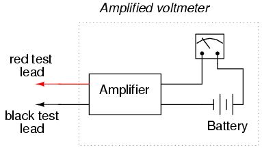
The internal workings of an amplifier are too complex to be discussed at this point, but suffice it to say that the circuit allows the measured voltage to control how much battery current is sent to the meter movement. Thus, the movement's current needs are supplied by a battery internal to the voltmeter and not by the circuit under test. The amplifier still loads the circuit under test to some degree, but generally hundreds or thousands of times less than the meter movement would by itself.
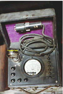
Before the advent of semiconductors known as "field-effect transistors," vacuum tubes were used as amplifying devices to perform this boosting. Such vacuum-tube voltmeters, or (VTVM's) were once very popular instruments for electronic test and measurement. Here is a photograph of a very old VTVM, with the vacuum tube exposed!
Now, solid-state transistor amplifier circuits accomplish the same task in digital meter designs. While this approach (of using an amplifier to boost the measured signal current) works well, it vastly complicates the design of the meter, making it nearly impossible for the beginning electronics student to comprehend its internal workings.
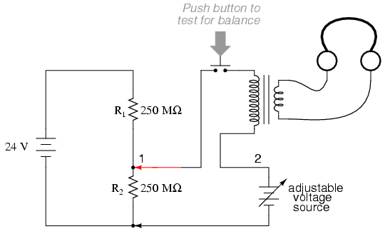
A final, and ingenious, solution to the problem of voltmeter loading is that of the potentiometric or null-balance instrument. It requires no advanced (electronic) circuitry or sensitive devices like transistors or vacuum tubes, but it does require greater technician involvement and skill. In a potentiometric instrument, a precision adjustable voltage source is compared against the measured voltage, and a sensitive device called a null detector is used to indicate when the two voltages are equal. In some circuit designs, a precision potentiometer is used to provide the adjustable voltage, hence the label potentiometric. When the voltages are equal, there will be zero current drawn from the circuit under test, and thus the measured voltage should be unaffected. It is easy to show how this works with our last example, the high-resistance voltage divider circuit:

The "null detector" is a sensitive device capable of indicating the presence of very small voltages. If an electromechanical meter movement is used as the null detector, it will have a spring-centered needle that can deflect in either direction so as to be useful for indicating a voltage of either polarity. As the purpose of a null detector is to accurately indicate a condition of zero voltage, rather than to indicate any specific (nonzero) quantity as a normal voltmeter would, the scale of the instrument used is irrelevant. Null detectors are typically designed to be as sensitive as possible in order to more precisely indicate a "null" or "balance" (zero voltage) condition.
An extremely simple type of null detector is a set of audio headphones, the speakers within acting as a kind of meter movement. When a DC voltage is initially applied to a speaker, the resulting current through it will move the speaker cone and produce an audible "click." Another "click" sound will be heard when the DC source is disconnected. Building on this principle, a sensitive null detector may be made from nothing more than headphones and a momentary contact switch:

If a set of "8 ohm" headphones are used for this purpose, its sensitivity may be greatly increased by connecting it to a device called a transformer. The transformer exploits principles of electromagnetism to "transform" the voltage and current levels of electrical energy pulses. In this case, the type of transformer used is a step-down transformer, and it converts low-current pulses (created by closing and opening the pushbutton switch while connected to a small voltage source) into higher-current pulses to more efficiently drive the speaker cones inside the headphones. An "audio output" transformer with an impedance ratio of 1000:8 is ideal for this purpose. The transformer also increases detector sensitivity by accumulating the energy of a low-current signal in a magnetic field for sudden release into the headphone speakers when the switch is opened. Thus, it will produce louder "clicks" for detecting smaller signals:

Connected to the potentiometric circuit as a null detector, the switch/transformer/headphone arrangement is used as such:
The purpose of any null detector is to act like a laboratory balance scale, indicating when the two voltages are equal (absence of voltage between points 1 and 2) and nothing more. The laboratory scale balance beam doesn't actually weight anything; rather, it simply indicates equality between the unknown mass and the pile of standard (calibrated) masses.
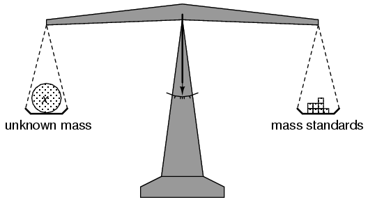
Likewise, the null detector simply indicates when the voltage between points 1 and 2 are equal, which (according to Kirchhoff's Voltage Law) will be when the adjustable voltage source (the battery symbol with a diagonal arrow going through it) is precisely equal in voltage to the drop across R2.
To operate this instrument, the technician would manually adjust the output of the precision voltage source until the null detector indicated exactly zero (if using audio headphones as the null detector, the technician would repeatedly press and release the pushbutton switch, listening for silence to indicate that the circuit was "balanced"), and then note the source voltage as indicated by a voltmeter connected across the precision voltage source, that indication being representative of the voltage across the lower 250 MΩ resistor:
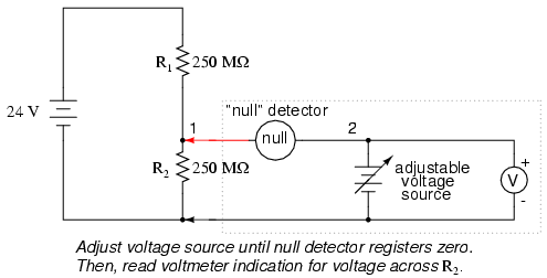
The voltmeter used to directly measure the precision source need not have an extremely high Ω/V sensitivity, because the source will supply all the current it needs to operate. So long as there is zero voltage across the null detector, there will be zero current between points 1 and 2, equating to no loading of the divider circuit under test.
It is worthy to reiterate the fact that this method, properly executed, places almost zero load upon the measured circuit. Ideally, it places absolutely no load on the tested circuit, but to achieve this ideal goal the null detector would have to have absolutely zero voltage across it, which would require an infinitely sensitive null meter and a perfect balance of voltage from the adjustable voltage source. However, despite its practical inability to achieve absolute zero loading, a potentiometric circuit is still an excellent technique for measuring voltage in high-resistance circuits. And unlike the electronic amplifier solution, which solves the problem with advanced technology, the potentiometric method achieves a hypothetically perfect solution by exploiting a fundamental law of electricity (KVL).
- REVIEW:
- An ideal voltmeter has infinite resistance.
- Too low of an internal resistance in a voltmeter will adversely affect the circuit being measured.
- Vacuum tube voltmeters (VTVM's), transistor voltmeters, and potentiometric circuits are all means of minimizing the load placed on a measured circuit. Of these methods, the potentiometric ("null-balance") technique is the only one capable of placing zero load on the circuit.
- A null detector is a device built for maximum sensitivity to small voltages or currents. It is used in potentiometric voltmeter circuits to indicate the absence of voltage between two points, thus indicating a condition of balance between an adjustable voltage source and the voltage being measured.
Ammeter design
A meter designed to measure electrical current is popularly called an "ammeter" because the unit of measurement is "amps."
In ammeter designs, external resistors added to extend the usable range of the movement are connected in parallel with the movement rather than in series as is the case for voltmeters. This is because we want to divide the measured current, not the measured voltage, going to the movement, and because current divider circuits are always formed by parallel resistances.
Taking the same meter movement as the voltmeter example, we can see that it would make a very limited instrument by itself, full-scale deflection occurring at only 1 mA:
As is the case with extending a meter movement's voltage-measuring ability, we would have to correspondingly re-label the movement's scale so that it read differently for an extended current range. For example, if we wanted to design an ammeter to have a full-scale range of 5 amps using the same meter movement as before (having an intrinsic full-scale range of only 1 mA), we would have to re-label the movement's scale to read 0 A on the far left and 5 A on the far right, rather than 0 mA to 1 mA as before. Whatever extended range provided by the parallel-connected resistors, we would have to represent graphically on the meter movement face.
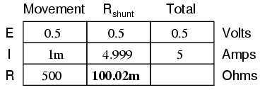
Using 5 amps as an extended range for our sample movement, let's determine the amount of parallel resistance necessary to "shunt," or bypass, the majority of current so that only 1 mA will go through the movement with a total current of 5 A:

From our given values of movement current, movement resistance, and total circuit (measured) current, we can determine the voltage across the meter movement (Ohm's Law applied to the center column, E=IR):

Knowing that the circuit formed by the movement and the shunt is of a parallel configuration, we know that the voltage across the movement, shunt, and test leads (total) must be the same:

We also know that the current through the shunt must be the difference between the total current (5 amps) and the current through the movement (1 mA), because branch currents add in a parallel configuration:

Then, using Ohm's Law (R=E/I) in the right column, we can determine the necessary shunt resistance:
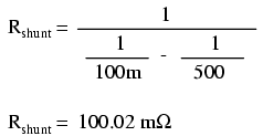
Of course, we could have calculated the same value of just over 100 milli-ohms (100 mΩ) for the shunt by calculating total resistance (R=E/I; 0.5 volts/5 amps = 100 mΩ exactly), then working the parallel resistance formula backwards, but the arithmetic would have been more challenging:
In real life, the shunt resistor of an ammeter will usually be encased within the protective metal housing of the meter unit, hidden from sight. Note the construction of the ammeter in the following photograph:

This particular ammeter is an automotive unit manufactured by Stewart-Warner. Although the D'Arsonval meter movement itself probably has a full scale rating in the range of milliamps, the meter as a whole has a range of +/- 60 amps. The shunt resistor providing this high current range is enclosed within the metal housing of the meter. Note also with this particular meter that the needle centers at zero amps and can indicate either a "positive" current or a "negative" current. Connected to the battery charging circuit of an automobile, this meter is able to indicate a charging condition (electrons flowing from generator to battery) or a discharging condition (electrons flowing from battery to the rest of the car's loads).
As is the case with multiple-range voltmeters, ammeters can be given more than one usable range by incorporating several shunt resistors switched with a multi-pole switch:

Notice that the range resistors are connected through the switch so as to be in parallel with the meter movement, rather than in series as it was in the voltmeter design. The five-position switch makes contact with only one resistor at a time, of course. Each resistor is sized accordingly for a different full-scale range, based on the particular rating of the meter movement (1 mA, 500 Ω).
With such a meter design, each resistor value is determined by the same technique, using a known total current, movement full-scale deflection rating, and movement resistance. For an ammeter with ranges of 100 mA, 1 A, 10 A, and 100 A, the shunt resistances would be as such:

Notice that these shunt resistor values are very low! 5.00005 mΩ is 5.00005 milli-ohms, or 0.00500005 ohms! To achieve these low resistances, ammeter shunt resistors often have to be custom-made from relatively large-diameter wire or solid pieces of metal.
One thing to be aware of when sizing ammeter shunt resistors is the factor of power dissipation. Unlike the voltmeter, an ammeter's range resistors have to carry large amounts of current. If those shunt resistors are not sized accordingly, they may overheat and suffer damage, or at the very least lose accuracy due to overheating. For the example meter above, the power dissipations at full-scale indication are (the double-squiggly lines represent "approximately equal to" in mathematics):
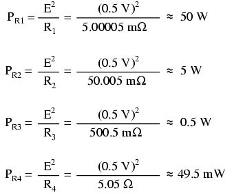
An 1/8 watt resistor would work just fine for R4, a 1/2 watt resistor would suffice for R3 and a 5 watt for R2 (although resistors tend to maintain their long-term accuracy better if not operated near their rated power dissipation, so you might want to over-rate resistors R2 and R3), but precision 50 watt resistors are rare and expensive components indeed. A custom resistor made from metal stock or thick wire may have to be constructed for R1 to meet both the requirements of low resistance and high power rating.
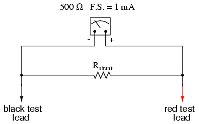
Sometimes, shunt resistors are used in conjunction with voltmeters of high input resistance to measure current. In these cases, the current through the voltmeter movement is small enough to be considered negligible, and the shunt resistance can be sized according to how many volts or millivolts of drop will be produced per amp of current:
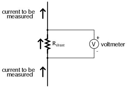
If, for example, the shunt resistor in the above circuit were sized at precisely 1 Ω, there would be 1 volt dropped across it for every amp of current through it. The voltmeter indication could then be taken as a direct indication of current through the shunt. For measuring very small currents, higher values of shunt resistance could be used to generate more voltage drop per given unit of current, thus extending the usable range of the (volt)meter down into lower amounts of current. The use of voltmeters in conjunction with low-value shunt resistances for the measurement of current is something commonly seen in industrial applications.
The use of a shunt resistor along with a voltmeter to measure current can be a useful trick for simplifying the task of frequent current measurements in a circuit. Normally, to measure current through a circuit with an ammeter, the circuit would have to be broken (interrupted) and the ammeter inserted between the separated wire ends, like this:
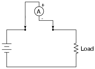
If we have a circuit where current needs to be measured often, or we would just like to make the process of current measurement more convenient, a shunt resistor could be placed between those points and left their permanently, current readings taken with a voltmeter as needed without interrupting continuity in the circuit:

Of course, care must be taken in sizing the shunt resistor low enough so that it doesn't adversely affect the circuit's normal operation, but this is generally not difficult to do. This technique might also be useful in computer circuit analysis, where we might want to have the computer display current through a circuit in terms of a voltage (with SPICE, this would allow us to avoid the idiosyncrasy of reading negative current values):

shunt resistor example circuit
v1 1 0
rshunt 1 2 1
rload 2 0 15k
.dc v1 12 12 1
.print dc v(1,2)
.end
v1            v(1,2)
1.200E+01     7.999E-04
We would interpret the voltage reading across the shunt resistor (between circuit nodes 1 and 2 in the SPICE simulation) directly as amps, with 7.999E-04 being 0.7999 mA, or 799.9 µA. Ideally, 12 volts applied directly across 15 kΩ would give us exactly 0.8 mA, but the resistance of the shunt lessens that current just a tiny bit (as it would in real life). However, such a tiny error is generally well within acceptable limits of accuracy for either a simulation or a real circuit, and so shunt resistors can be used in all but the most demanding applications for accurate current measurement.
- REVIEW:
- Ammeter ranges are created by adding parallel "shunt" resistors to the movement circuit, providing a precise current division.
- Shunt resistors may have high power dissipations, so be careful when choosing parts for such meters!
- Shunt resistors can be used in conjunction with high-resistance voltmeters as well as low-resistance ammeter movements, producing accurate voltage drops for given amounts of current. Shunt resistors should be selected for as low a resistance value as possible to minimize their impact upon the circuit under test.
Ammeter impact on measured circuit
Just like voltmeters, ammeters tend to influence the amount of current in the circuits they're connected to. However, unlike the ideal voltmeter, the ideal ammeter has zero internal resistance, so as to drop as little voltage as possible as electrons flow through it. Note that this ideal resistance value is exactly opposite as that of a voltmeter. With voltmeters, we want as little current to be drawn as possible from the circuit under test. With ammeters, we want as little voltage to be dropped as possible while conducting current.
Here is an extreme example of an ammeter's effect upon a circuit:
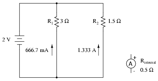
With the ammeter disconnected from this circuit, the current through the 3 Ω resistor would be 666.7 mA, and the current through the 1.5 Ω resistor would be 1.33 amps. If the ammeter had an internal resistance of 1/2 Ω, and it were inserted into one of the branches of this circuit, though, its resistance would seriously affect the measured branch current:
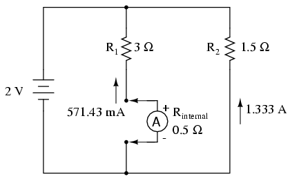
Having effectively increased the left branch resistance from 3 Ω to 3.5 Ω, the ammeter will read 571.43 mA instead of 666.7 mA. Placing the same ammeter in the right branch would affect the current to an even greater extent:

Now the right branch current is 1 amp instead of 1.333 amps, due to the increase in resistance created by the addition of the ammeter into the current path.
When using standard ammeters that connect in series with the circuit being measured, it might not be practical or possible to redesign the meter for a lower input (lead-to-lead) resistance. However, if we were selecting a value of shunt resistor to place in the circuit for a current measurement based on voltage drop, and we had our choice of a wide range of resistances, it would be best to choose the lowest practical resistance for the application. Any more resistance than necessary and the shunt may impact the circuit adversely by adding excessive resistance in the current path.
One ingenious way to reduce the impact that a current-measuring device has on a circuit is to use the circuit wire as part of the ammeter movement itself. All current-carrying wires produce a magnetic field, the strength of which is in direct proportion to the strength of the current. By building an instrument that measures the strength of that magnetic field, a no-contact ammeter can be produced. Such a meter is able to measure the current through a conductor without even having to make physical contact with the circuit, much less break continuity or insert additional resistance.

Ammeters of this design are made, and are called "clamp-on" meters because they have "jaws" which can be opened and then secured around a circuit wire. Clamp-on ammeters make for quick and safe current measurements, especially on high-power industrial circuits. Because the circuit under test has had no additional resistance inserted into it by a clamp-on meter, there is no error induced in taking a current measurement.

The actual movement mechanism of a clamp-on ammeter is much the same as for an iron-vane instrument, except that there is no internal wire coil to generate the magnetic field. More modern designs of clamp-on ammeters utilize a small magnetic field detector device called a Hall-effect sensor to accurately determine field strength. Some clamp-on meters contain electronic amplifier circuitry to generate a small voltage proportional to the current in the wire between the jaws, that small voltage connected to a voltmeter for convenient readout by a technician. Thus, a clamp-on unit can be an accessory device to a voltmeter, for current measurement.
A less accurate type of magnetic-field-sensing ammeter than the clamp-on style is shown in the following photograph:

The operating principle for this ammeter is identical to the clamp-on style of meter: the circular magnetic field surrounding a current-carrying conductor deflects the meter's needle, producing an indication on the scale. Note how there are two current scales on this particular meter: +/- 75 amps and +/- 400 amps. These two measurement scales correspond to the two sets of notches on the back of the meter. Depending on which set of notches the current-carrying conductor is laid in, a given strength of magnetic field will have a different amount of effect on the needle. In effect, the two different positions of the conductor relative to the movement act as two different range resistors in a direct-connection style of ammeter.
- REVIEW:
- An ideal ammeter has zero resistance.
- A "clamp-on" ammeter measures current through a wire by measuring the strength of the magnetic field around it rather than by becoming part of the circuit, making it an ideal ammeter.
- Clamp-on meters make for quick and safe current measurements, because there is no conductive contact between the meter and the circuit.
Ohmmeter design
Though mechanical ohmmeter (resistance meter) designs are rarely used today, having largely been superseded by digital instruments, their operation is nonetheless intriguing and worthy of study.
The purpose of an ohmmeter, of course, is to measure the resistance placed between its leads. This resistance reading is indicated through a mechanical meter movement which operates on electric current. The ohmmeter must then have an internal source of voltage to create the necessary current to operate the movement, and also have appropriate ranging resistors to allow just the right amount of current through the movement at any given resistance.
Starting with a simple movement and battery circuit, let's see how it would function as an ohmmeter:

When there is infinite resistance (no continuity between test leads), there is zero current through the meter movement, and the needle points toward the far left of the scale. In this regard, the ohmmeter indication is "backwards" because maximum indication (infinity) is on the left of the scale, while voltage and current meters have zero at the left of their scales.
If the test leads of this ohmmeter are directly shorted together (measuring zero Ω), the meter movement will have a maximum amount of current through it, limited only by the battery voltage and the movement's internal resistance:
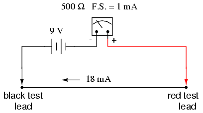
With 9 volts of battery potential and only 500 Ω of movement resistance, our circuit current will be 18 mA, which is far beyond the full-scale rating of the movement. Such an excess of current will likely damage the meter.
Not only that, but having such a condition limits the usefulness of the device. If full left-of-scale on the meter face represents an infinite amount of resistance, then full right-of-scale should represent zero. Currently, our design "pegs" the meter movement hard to the right when zero resistance is attached between the leads. We need a way to make it so that the movement just registers full-scale when the test leads are shorted together. This is accomplished by adding a series resistance to the meter's circuit:

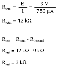
To determine the proper value for R, we calculate the total circuit resistance needed to limit current to 1 mA (full-scale deflection on the movement) with 9 volts of potential from the battery, then subtract the movement's internal resistance from that figure:

Now that the right value for R has been calculated, we're still left with a problem of meter range. On the left side of the scale we have "infinity" and on the right side we have zero. Besides being "backwards" from the scales of voltmeters and ammeters, this scale is strange because it goes from nothing to everything, rather than from nothing to a finite value (such as 10 volts, 1 amp, etc.). One might pause to wonder, "what does middle-of-scale represent? What figure lies exactly between zero and infinity?" Infinity is more than just a very big amount: it is an incalculable quantity, larger than any definite number ever could be. If half-scale indication on any other type of meter represents 1/2 of the full-scale range value, then what is half of infinity on an ohmmeter scale?
The answer to this paradox is a logarithmic scale. Simply put, the scale of an ohmmeter does not smoothly progress from zero to infinity as the needle sweeps from right to left. Rather, the scale starts out "expanded" at the right-hand side, with the successive resistance values growing closer and closer to each other toward the left side of the scale:

Infinity cannot be approached in a linear (even) fashion, because the scale would never get there! With a logarithmic scale, the amount of resistance spanned for any given distance on the scale increases as the scale progresses toward infinity, making infinity an attainable goal.
We still have a question of range for our ohmmeter, though. What value of resistance between the test leads will cause exactly 1/2 scale deflection of the needle? If we know that the movement has a full-scale rating of 1 mA, then 0.5 mA (500 µA) must be the value needed for half-scale deflection. Following our design with the 9 volt battery as a source we get:

With an internal movement resistance of 500 Ω and a series range resistor of 8.5 kΩ, this leaves 9 kΩ for an external (lead-to-lead) test resistance at 1/2 scale. In other words, the test resistance giving 1/2 scale deflection in an ohmmeter is equal in value to the (internal) series total resistance of the meter circuit.
Using Ohm's Law a few more times, we can determine the test resistance value for 1/4 and 3/4 scale deflection as well:
1/4 scale deflection (0.25 mA of meter current):

3/4 scale deflection (0.75 mA of meter current):
So, the scale for this ohmmeter looks something like this:

One major problem with this design is its reliance upon a stable battery voltage for accurate resistance reading. If the battery voltage decreases (as all chemical batteries do with age and use), the ohmmeter scale will lose accuracy. With the series range resistor at a constant value of 8.5 kΩ and the battery voltage decreasing, the meter will no longer deflect full-scale to the right when the test leads are shorted together (0 Ω). Likewise, a test resistance of 9 kΩ will fail to deflect the needle to exactly 1/2 scale with a lesser battery voltage.
There are design techniques used to compensate for varying battery voltage, but they do not completely take care of the problem and are to be considered approximations at best. For this reason, and for the fact of the logarithmic scale, this type of ohmmeter is never considered to be a precision instrument.
One final caveat needs to be mentioned with regard to ohmmeters: they only function correctly when measuring resistance that is not being powered by a voltage or current source. In other words, you cannot measure resistance with an ohmmeter on a "live" circuit! The reason for this is simple: the ohmmeter's accurate indication depends on the only source of voltage being its internal battery. The presence of any voltage across the component to be measured will interfere with the ohmmeter's operation. If the voltage is large enough, it may even damage the ohmmeter.
- REVIEW:
- Ohmmeters contain internal sources of voltage to supply power in taking resistance measurements.
- An analog ohmmeter scale is "backwards" from that of a voltmeter or ammeter, the movement needle reading zero resistance at full-scale and infinite resistance at rest.
- Analog ohmmeters also have logarithmic scales, "expanded" at the low end of the scale and "compressed" at the high end to be able to span from zero to infinite resistance.
- Analog ohmmeters are not precision instruments.
- Ohmmeters should never be connected to an energized circuit (that is, a circuit with its own source of voltage). Any voltage applied to the test leads of an ohmmeter will invalidate its reading.
High voltage ohmmeters
Most ohmmeters of the design shown in the previous section utilize a battery of relatively low voltage, usually nine volts or less. This is perfectly adequate for measuring resistances under several mega-ohms (MΩ), but when extremely high resistances need to be measured, a 9 volt battery is insufficient for generating enough current to actuate an electromechanical meter movement.
Also, as discussed in an earlier chapter, resistance is not always a stable (linear) quantity. This is especially true of non-metals. Recall the graph of current over voltage for a small air gap (less than an inch):

While this is an extreme example of nonlinear conduction, other substances exhibit similar insulating/conducting properties when exposed to high voltages. Obviously, an ohmmeter using a low-voltage battery as a source of power cannot measure resistance at the ionization potential of a gas, or at the breakdown voltage of an insulator. If such resistance values need to be measured, nothing but a high-voltage ohmmeter will suffice.
The most direct method of high-voltage resistance measurement involves simply substituting a higher voltage battery in the same basic design of ohmmeter investigated earlier:

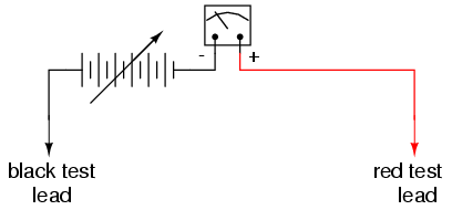
Knowing, however, that the resistance of some materials tends to change with applied voltage, it would be advantageous to be able to adjust the voltage of this ohmmeter to obtain resistance measurements under different conditions:
Unfortunately, this would create a calibration problem for the meter. If the meter movement deflects full-scale with a certain amount of current through it, the full-scale range of the meter in ohms would change as the source voltage changed. Imagine connecting a stable resistance across the test leads of this ohmmeter while varying the source voltage: as the voltage is increased, there will be more current through the meter movement, hence a greater amount of deflection. What we really need is a meter movement that will produce a consistent, stable deflection for any stable resistance value measured, regardless of the applied voltage.
Accomplishing this design goal requires a special meter movement, one that is peculiar to megohmmeters, or meggers, as these instruments are known.
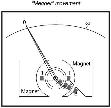
The numbered, rectangular blocks in the above illustration are cross-sectional representations of wire coils. These three coils all move with the needle mechanism. There is no spring mechanism to return the needle to a set position. When the movement is unpowered, the needle will randomly "float." The coils are electrically connected like this:
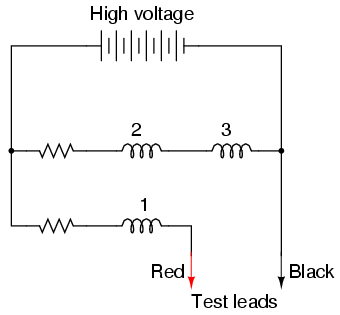
With infinite resistance between the test leads (open circuit), there will be no current through coil 1, only through coils 2 and 3. When energized, these coils try to center themselves in the gap between the two magnet poles, driving the needle fully to the right of the scale where it points to "infinity."
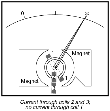
Any current through coil 1 (through a measured resistance connected between the test leads) tends to drive the needle to the left of scale, back to zero. The internal resistor values of the meter movement are calibrated so that when the test leads are shorted together, the needle deflects exactly to the 0 Ω position.
Because any variations in battery voltage will affect the torque generated by both sets of coils (coils 2 and 3, which drive the needle to the right, and coil 1, which drives the needle to the left), those variations will have no effect of the calibration of the movement. In other words, the accuracy of this ohmmeter movement is unaffected by battery voltage: a given amount of measured resistance will produce a certain needle deflection, no matter how much or little battery voltage is present.
The only effect that a variation in voltage will have on meter indication is the degree to which the measured resistance changes with applied voltage. So, if we were to use a megger to measure the resistance of a gas-discharge lamp, it would read very high resistance (needle to the far right of the scale) for low voltages and low resistance (needle moves to the left of the scale) for high voltages. This is precisely what we expect from a good high-voltage ohmmeter: to provide accurate indication of subject resistance under different circumstances.
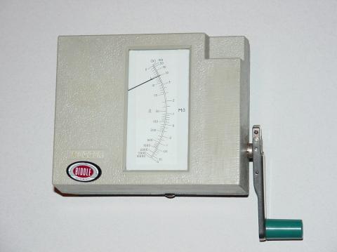
For maximum safety, most meggers are equipped with hand-crank generators for producing the high DC voltage (up to 1000 volts). If the operator of the meter receives a shock from the high voltage, the condition will be self-correcting, as he or she will naturally stop cranking the generator! Sometimes a "slip clutch" is used to stabilize generator speed under different cranking conditions, so as to provide a fairly stable voltage whether it is cranked fast or slow. Multiple voltage output levels from the generator are available by the setting of a selector switch.
A simple hand-crank megger is shown in this photograph:
Some meggers are battery-powered to provide greater precision in output voltage. For safety reasons these meggers are activated by a momentary-contact pushbutton switch, so the switch cannot be left in the "on" position and pose a significant shock hazard to the meter operator.
Real meggers are equipped with three connection terminals, labeled Line, Earth, and Guard. The schematic is quite similar to the simplified version shown earlier:

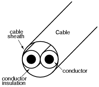
Resistance is measured between the Line and Earth terminals, where current will travel through coil 1. The "Guard" terminal is provided for special testing situations where one resistance must be isolated from another. Take for instance this scenario where the insulation resistance is to be tested in a two-wire cable:
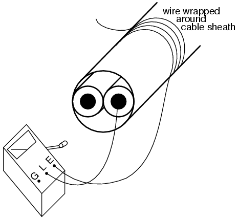
To measure insulation resistance from a conductor to the outside of the cable, we need to connect the "Line" lead of the megger to one of the conductors and connect the "Earth" lead of the megger to a wire wrapped around the sheath of the cable:
In this configuration the megger should read the resistance between one conductor and the outside sheath. Or will it? If we draw a schematic diagram showing all insulation resistances as resistor symbols, what we have looks like this:
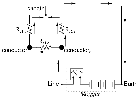
Rather than just measure the resistance of the second conductor to the sheath (Rc2-s), what we'll actually measure is that resistance in parallel with the series combination of conductor-to-conductor resistance (Rc1-c2) and the first conductor to the sheath (Rc1-s). If we don't care about this fact, we can proceed with the test as configured. If we desire to measure only the resistance between the second conductor and the sheath (Rc2-s), then we need to use the megger's "Guard" terminal:

Now the circuit schematic looks like this:

Connecting the "Guard" terminal to the first conductor places the two conductors at almost equal potential. With little or no voltage between them, the insulation resistance is nearly infinite, and thus there will be no current between the two conductors. Consequently, the megger's resistance indication will be based exclusively on the current through the second conductor's insulation, through the cable sheath, and to the wire wrapped around, not the current leaking through the first conductor's insulation.
Meggers are field instruments: that is, they are designed to be portable and operated by a technician on the job site with as much ease as a regular ohmmeter. They are very useful for checking high-resistance "short" failures between wires caused by wet or degraded insulation. Because they utilize such high voltages, they are not as affected by stray voltages (voltages less than 1 volt produced by electrochemical reactions between conductors, or "induced" by neighboring magnetic fields) as ordinary ohmmeters.
For a more thorough test of wire insulation, another high-voltage ohmmeter commonly called a hi-pot tester is used. These specialized instruments produce voltages in excess of 1 kV, and may be used for testing the insulating effectiveness of oil, ceramic insulators, and even the integrity of other high-voltage instruments. Because they are capable of producing such high voltages, they must be operated with the utmost care, and only by trained personnel.
It should be noted that hi-pot testers and even meggers (in certain conditions) are capable of damaging wire insulation if incorrectly used. Once an insulating material has been subjected to breakdown by the application of an excessive voltage, its ability to electrically insulate will be compromised. Again, these instruments are to be used only by trained personnel.
Multimeters
Seeing as how a common meter movement can be made to function as a voltmeter, ammeter, or ohmmeter simply by connecting it to different external resistor networks, it should make sense that a multi-purpose meter ("multimeter") could be designed in one unit with the appropriate switch(es) and resistors.
For general purpose electronics work, the multimeter reigns supreme as the instrument of choice. No other device is able to do so much with so little an investment in parts and elegant simplicity of operation. As with most things in the world of electronics, the advent of solid-state components like transistors has revolutionized the way things are done, and multimeter design is no exception to this rule. However, in keeping with this chapter's emphasis on analog ("old-fashioned") meter technology, I'll show you a few pre-transistor meters.

The unit shown above is typical of a handheld analog multimeter, with ranges for voltage, current, and resistance measurement. Note the many scales on the face of the meter movement for the different ranges and functions selectable by the rotary switch. The wires for connecting this instrument to a circuit (the "test leads") are plugged into the two copper jacks (socket holes) at the bottom-center of the meter face marked "- TEST +", black and red.
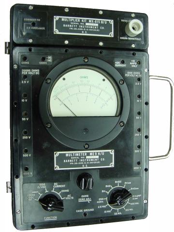
This multimeter (Barnett brand) takes a slightly different design approach than the previous unit. Note how the rotary selector switch has fewer positions than the previous meter, but also how there are many more jacks into which the test leads may be plugged into. Each one of those jacks is labeled with a number indicating the respective full-scale range of the meter.

Lastly, here is a picture of a digital multimeter. Note that the familiar meter movement has been replaced by a blank, gray-colored display screen. When powered, numerical digits appear in that screen area, depicting the amount of voltage, current, or resistance being measured. This particular brand and model of digital meter has a rotary selector switch and four jacks into which test leads can be plugged. Two leads -- one red and one black -- are shown plugged into the meter.
A close examination of this meter will reveal one "common" jack for the black test lead and three others for the red test lead. The jack into which the red lead is shown inserted is labeled for voltage and resistance measurement, while the other two jacks are labeled for current (A, mA, and µA) measurement. This is a wise design feature of the multimeter, requiring the user to move a test lead plug from one jack to another in order to switch from the voltage measurement to the current measurement function. It would be hazardous to have the meter set in current measurement mode while connected across a significant source of voltage because of the low input resistance, and making it necessary to move a test lead plug rather than just flip the selector switch to a different position helps ensure that the meter doesn't get set to measure current unintentionally.
Note that the selector switch still has different positions for voltage and current measurement, so in order for the user to switch between these two modes of measurement they must switch the position of the red test lead and move the selector switch to a different position.
Also note that neither the selector switch nor the jacks are labeled with measurement ranges. In other words, there are no "100 volt" or "10 volt" or "1 volt" ranges (or any equivalent range steps) on this meter. Rather, this meter is "autoranging," meaning that it automatically picks the appropriate range for the quantity being measured. Autoranging is a feature only found on digital meters, but not all digital meters.
No two models of multimeters are designed to operate exactly the same, even if they're manufactured by the same company. In order to fully understand the operation of any multimeter, the owner's manual must be consulted.
Here is a schematic for a simple analog volt/ammeter:

In the switch's three lower (most counter-clockwise) positions, the meter movement is connected to the Common and V jacks through one of three different series range resistors (Rmultiplier1 through Rmultiplier3), and so acts as a voltmeter. In the fourth position, the meter movement is connected in parallel with the shunt resistor, and so acts as an ammeter for any current entering the common jack and exiting the A jack. In the last (furthest clockwise) position, the meter movement is disconnected from either red jack, but short-circuited through the switch. This short-circuiting creates a dampening effect on the needle, guarding against mechanical shock damage when the meter is handled and moved.
If an ohmmeter function is desired in this multimeter design, it may be substituted for one of the three voltage ranges as such:

With all three fundamental functions available, this multimeter may also be known as a volt-ohm-milliammeter.
Obtaining a reading from an analog multimeter when there is a multitude of ranges and only one meter movement may seem daunting to the new technician. On an analog multimeter, the meter movement is marked with several scales, each one useful for at least one range setting. Here is a close-up photograph of the scale from the Barnett multimeter shown earlier in this section:
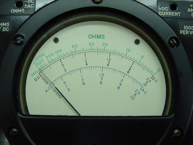
Note that there are three types of scales on this meter face: a green scale for resistance at the top, a set of black scales for DC voltage and current in the middle, and a set of blue scales for AC voltage and current at the bottom. Both the DC and AC scales have three sub-scales, one ranging 0 to 2.5, one ranging 0 to 5, and one ranging 0 to 10. The meter operator must choose whichever scale best matches the range switch and plug settings in order to properly interpret the meter's indication.
This particular multimeter has several basic voltage measurement ranges: 2.5 volts, 10 volts, 50 volts, 250 volts, 500 volts, and 1000 volts. With the use of the voltage range extender unit at the top of the multimeter, voltages up to 5000 volts can be measured. Suppose the meter operator chose to switch the meter into the "volt" function and plug the red test lead into the 10 volt jack. To interpret the needle's position, he or she would have to read the scale ending with the number "10". If they moved the red test plug into the 250 volt jack, however, they would read the meter indication on the scale ending with "2.5", multiplying the direct indication by a factor of 100 in order to find what the measured voltage was.
If current is measured with this meter, another jack is chosen for the red plug to be inserted into and the range is selected via a rotary switch. This close-up photograph shows the switch set to the 2.5 mA position:
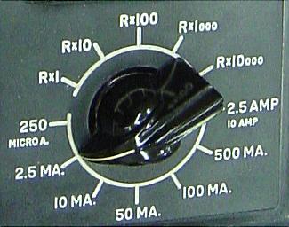
Note how all current ranges are power-of-ten multiples of the three scale ranges shown on the meter face: 2.5, 5, and 10. In some range settings, such as the 2.5 mA for example, the meter indication may be read directly on the 0 to 2.5 scale. For other range settings (250 µA, 50 mA, 100 mA, and 500 mA), the meter indication must be read off the appropriate scale and then multiplied by either 10 or 100 to obtain the real figure. The highest current range available on this meter is obtained with the rotary switch in the 2.5/10 amp position. The distinction between 2.5 amps and 10 amps is made by the red test plug position: a special "10 amp" jack next to the regular current-measuring jack provides an alternative plug setting to select the higher range.
Resistance in ohms, of course, is read by a logarithmic scale at the top of the meter face. It is "backward," just like all battery-operated analog ohmmeters, with zero at the right-hand side of the face and infinity at the left-hand side. There is only one jack provided on this particular multimeter for "ohms," so different resistance-measuring ranges must be selected by the rotary switch. Notice on the switch how five different "multiplier" settings are provided for measuring resistance: Rx1, Rx10, Rx100, Rx1000, and Rx10000. Just as you might suspect, the meter indication is given by multiplying whatever needle position is shown on the meter face by the power-of-ten multiplying factor set by the rotary switch.
Kelvin (4-wire) resistance measurement
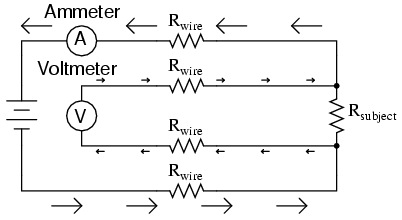
Suppose we wished to measure the resistance of some component located a significant distance away from our ohmmeter. Such a scenario would be problematic, because an ohmmeter measures all resistance in the circuit loop, which includes the resistance of the wires (Rwire) connecting the ohmmeter to the component being measured (Rsubject):
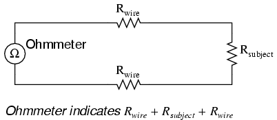
Usually, wire resistance is very small (only a few ohms per hundreds of feet, depending primarily on the gauge (size) of the wire), but if the connecting wires are very long, and/or the component to be measured has a very low resistance anyway, the measurement error introduced by wire resistance will be substantial.
An ingenious method of measuring the subject resistance in a situation like this involves the use of both an ammeter and a voltmeter. We know from Ohm's Law that resistance is equal to voltage divided by current (R = E/I). Thus, we should be able to determine the resistance of the subject component if we measure the current going through it and the voltage dropped across it:

Current is the same at all points in the circuit, because it is a series loop. Because we're only measuring voltage dropped across the subject resistance (and not the wires' resistances), though, the calculated resistance is indicative of the subject component's resistance (Rsubject) alone.
Our goal, though, was to measure this subject resistance from a distance, so our voltmeter must be located somewhere near the ammeter, connected across the subject resistance by another pair of wires containing resistance:
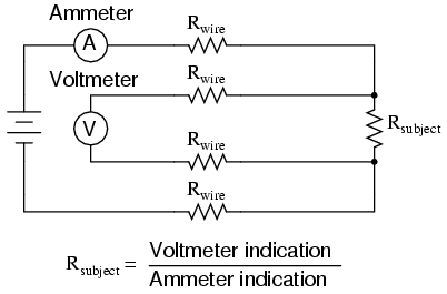
At first it appears that we have lost any advantage of measuring resistance this way, because the voltmeter now has to measure voltage through a long pair of (resistive) wires, introducing stray resistance back into the measuring circuit again. However, upon closer inspection it is seen that nothing is lost at all, because the voltmeter's wires carry miniscule current. Thus, those long lengths of wire connecting the voltmeter across the subject resistance will drop insignificant amounts of voltage, resulting in a voltmeter indication that is very nearly the same as if it were connected directly across the subject resistance:
Any voltage dropped across the main current-carrying wires will not be measured by the voltmeter, and so do not factor into the resistance calculation at all. Measurement accuracy may be improved even further if the voltmeter's current is kept to a minimum, either by using a high-quality (low full-scale current) movement and/or a potentiometric (null-balance) system.
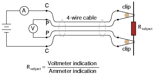
This method of measurement which avoids errors caused by wire resistance is called the Kelvin, or 4-wire method. Special connecting clips called Kelvin clips are made to facilitate this kind of connection across a subject resistance:

In regular, "alligator" style clips, both halves of the jaw are electrically common to each other, usually joined at the hinge point. In Kelvin clips, the jaw halves are insulated from each other at the hinge point, only contacting at the tips where they clasp the wire or terminal of the subject being measured. Thus, current through the "C" ("current") jaw halves does not go through the "P" ("potential," or voltage) jaw halves, and will not create any error-inducing voltage drop along their length:
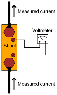
The same principle of using different contact points for current conduction and voltage measurement is used in precision shunt resistors for measuring large amounts of current. As discussed previously, shunt resistors function as current measurement devices by dropping a precise amount of voltage for every amp of current through them, the voltage drop being measured by a voltmeter. In this sense, a precision shunt resistor "converts" a current value into a proportional voltage value. Thus, current may be accurately measured by measuring voltage dropped across the shunt:
Current measurement using a shunt resistor and voltmeter is particularly well-suited for applications involving particularly large magnitudes of current. In such applications, the shunt resistor's resistance will likely be in the order of milliohms or microohms, so that only a modest amount of voltage will be dropped at full current. Resistance this low is comparable to wire connection resistance, which means voltage measured across such a shunt must be done so in such a way as to avoid detecting voltage dropped across the current-carrying wire connections, lest huge measurement errors be induced. In order that the voltmeter measure only the voltage dropped by the shunt resistance itself, without any stray voltages originating from wire or connection resistance, shunts are usually equipped with four connection terminals:
In metrological (metrology = "the science of measurement") applications, where accuracy is of paramount importance, highly precise "standard" resistors are also equipped with four terminals: two for carrying the measured current, and two for conveying the resistor's voltage drop to the voltmeter. This way, the voltmeter only measures voltage dropped across the precision resistance itself, without any stray voltages dropped across current-carrying wires or wire-to-terminal connection resistances.
The following photograph shows a precision standard resistor of 1 Ω value immersed in a temperature-controlled oil bath with a few other standard resistors. Note the two large, outer terminals for current, and the two small connection terminals for voltage:

Here is another, older (pre-World War II) standard resistor of German manufacture. This unit has a resistance of 0.001 Ω, and again the four terminal connection points can be seen as black knobs (metal pads underneath each knob for direct metal-to-metal connection with the wires), two large knobs for securing the current-carrying wires, and two smaller knobs for securing the voltmeter ("potential") wires:
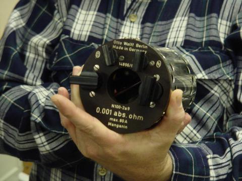
Appreciation is extended to the Fluke Corporation in Everett, Washington for allowing me to photograph these expensive and somewhat rare standard resistors in their primary standards laboratory.
It should be noted that resistance measurement using both an ammeter and a voltmeter is subject to compound error. Because the accuracy of both instruments factors in to the final result, the overall measurement accuracy may be worse than either instrument considered alone. For instance, if the ammeter is accurate to +/- 1% and the voltmeter is also accurate to +/- 1%, any measurement dependent on the indications of both instruments may be inaccurate by as much as +/- 2%.
Greater accuracy may be obtained by replacing the ammeter with a standard resistor, used as a current-measuring shunt. There will still be compound error between the standard resistor and the voltmeter used to measure voltage drop, but this will be less than with a voltmeter + ammeter arrangement because typical standard resistor accuracy far exceeds typical ammeter accuracy. Using Kelvin clips to make connection with the subject resistance, the circuit looks something like this:

All current-carrying wires in the above circuit are shown in "bold," to easily distinguish them from wires connecting the voltmeter across both resistances (Rsubject and Rstandard). Ideally, a potentiometric voltmeter is used to ensure as little current through the "potential" wires as possible.
Bridge circuits
No text on electrical metering could be called complete without a section on bridge circuits. These ingenious circuits make use of a null-balance meter to compare two voltages, just like the laboratory balance scale compares two weights and indicates when they're equal. Unlike the "potentiometer" circuit used to simply measure an unknown voltage, bridge circuits can be used to measure all kinds of electrical values, not the least of which being resistance.
The standard bridge circuit, often called a Wheatstone bridge, looks something like this:

When the voltage between point 1 and the negative side of the battery is equal to the voltage between point 2 and the negative side of the battery, the null detector will indicate zero and the bridge is said to be "balanced." The bridge's state of balance is solely dependent on the ratios of Ra/Rb and R1/R2, and is quite independent of the supply voltage (battery). To measure resistance with a Wheatstone bridge, an unknown resistance is connected in the place of Ra or Rb, while the other three resistors are precision devices of known value. Either of the other three resistors can be replaced or adjusted until the bridge is balanced, and when balance has been reached the unknown resistor value can be determined from the ratios of the known resistances.
A requirement for this to be a measurement system is to have a set of variable resistors available whose resistances are precisely known, to serve as reference standards. For example, if we connect a bridge circuit to measure an unknown resistance Rx, we will have to know the exact values of the other three resistors at balance to determine the value of Rx:

Each of the four resistances in a bridge circuit are referred to as arms. The resistor in series with the unknown resistance Rx (this would be Ra in the above schematic) is commonly called the rheostat of the bridge, while the other two resistors are called the ratio arms of the bridge.
Accurate and stable resistance standards, thankfully, are not that difficult to construct. In fact, they were some of the first electrical "standard" devices made for scientific purposes. Here is a photograph of an antique resistance standard unit:
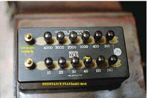
This resistance standard shown here is variable in discrete steps: the amount of resistance between the connection terminals could be varied with the number and pattern of removable copper plugs inserted into sockets.
Wheatstone bridges are considered a superior means of resistance measurement to the series battery-movement-resistor meter circuit discussed in the last section. Unlike that circuit, with all its nonlinearities (logarithmic scale) and associated inaccuracies, the bridge circuit is linear (the mathematics describing its operation are based on simple ratios and proportions) and quite accurate.
Given standard resistances of sufficient precision and a null detector device of sufficient sensitivity, resistance measurement accuracies of at least +/- 0.05% are attainable with a Wheatstone bridge. It is the preferred method of resistance measurement in calibration laboratories due to its high accuracy.
There are many variations of the basic Wheatstone bridge circuit. Most DC bridges are used to measure resistance, while bridges powered by alternating current (AC) may be used to measure different electrical quantities like inductance, capacitance, and frequency.
An interesting variation of the Wheatstone bridge is the Kelvin Double bridge, used for measuring very low resistances (typically less than 1/10 of an ohm). Its schematic diagram is as such:
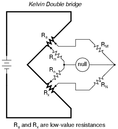
The low-value resistors are represented by thick-line symbols, and the wires connecting them to the voltage source (carrying high current) are likewise drawn thickly in the schematic. This oddly-configured bridge is perhaps best understood by beginning with a standard Wheatstone bridge set up for measuring low resistance, and evolving it step-by-step into its final form in an effort to overcome certain problems encountered in the standard Wheatstone configuration.
If we were to use a standard Wheatstone bridge to measure low resistance, it would look something like this:

When the null detector indicates zero voltage, we know that the bridge is balanced and that the ratios Ra/Rx and RM/RN are mathematically equal to each other. Knowing the values of Ra, RM, and RN therefore provides us with the necessary data to solve for Rx . . . almost.
We have a problem, in that the connections and connecting wires between Ra and Rx possess resistance as well, and this stray resistance may be substantial compared to the low resistances of Ra and Rx. These stray resistances will drop substantial voltage, given the high current through them, and thus will affect the null detector's indication and thus the balance of the bridge:
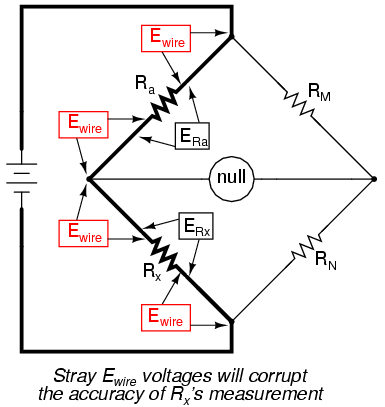
Since we don't want to measure these stray wire and connection resistances, but only measure Rx, we must find some way to connect the null detector so that it won't be influenced by voltage dropped across them. If we connect the null detector and RM/RN ratio arms directly across the ends of Ra and Rx, this gets us closer to a practical solution:
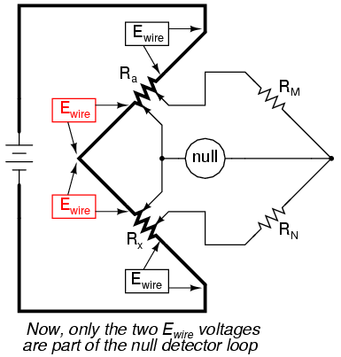
Now the top two Ewire voltage drops are of no effect to the null detector, and do not influence the accuracy of Rx's resistance measurement. However, the two remaining Ewire voltage drops will cause problems, as the wire connecting the lower end of Ra with the top end of Rx is now shunting across those two voltage drops, and will conduct substantial current, introducing stray voltage drops along its own length as well.
Knowing that the left side of the null detector must connect to the two near ends of Ra and Rx in order to avoid introducing those Ewire voltage drops into the null detector's loop, and that any direct wire connecting those ends of Ra and Rx will itself carry substantial current and create more stray voltage drops, the only way out of this predicament is to make the connecting path between the lower end of Ra and the upper end of Rx substantially resistive:
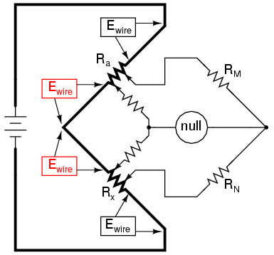
We can manage the stray voltage drops between Ra and Rx by sizing the two new resistors so that their ratio from upper to lower is the same ratio as the two ratio arms on the other side of the null detector. This is why these resistors were labeled Rm and Rn in the original Kelvin Double bridge schematic: to signify their proportionality with RM and RN:
With ratio Rm/Rn set equal to ratio RM/RN, rheostat arm resistor Ra is adjusted until the null detector indicates balance, and then we can say that Ra/Rx is equal to RM/RN, or simply find Rx by the following equation:

The actual balance equation of the Kelvin Double bridge is as follows (Rwire is the resistance of the thick, connecting wire between the low-resistance standard Ra and the test resistance Rx):
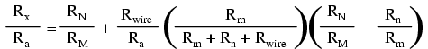
So long as the ratio between RM and RN is equal to the ratio between Rm and Rn, the balance equation is no more complex than that of a regular Wheatstone bridge, with Rx/Ra equal to RN/RM, because the last term in the equation will be zero, canceling the effects of all resistances except Rx, Ra, RM, and RN.
In many Kelvin Double bridge circuits, RM=Rm and RN=Rn. However, the lower the resistances of Rm and Rn, the more sensitive the null detector will be, because there is less resistance in series with it. Increased detector sensitivity is good, because it allows smaller imbalances to be detected, and thus a finer degree of bridge balance to be attained. Therefore, some high-precision Kelvin Double bridges use Rm and Rn values as low as 1/100 of their ratio arm counterparts (RM and RN, respectively). Unfortunately, though, the lower the values of Rm and Rn, the more current they will carry, which will increase the effect of any junction resistances present where Rm and Rn connect to the ends of Ra and Rx. As you can see, high instrument accuracy demands that all error-producing factors be taken into account, and often the best that can be achieved is a compromise minimizing two or more different kinds of errors.
- REVIEW:
- Bridge circuits rely on sensitive null-voltage meters to compare two voltages for equality.
- A Wheatstone bridge can be used to measure resistance by comparing unknown resistor against precision resistors of known value, much like a laboratory scale measures an unknown weight by comparing it against known standard weights.
- A Kelvin Double bridge is a variant of the Wheatstone bridge used for measuring very low resistances. Its additional complexity over the basic Wheatstone design is necessary for avoiding errors otherwise incurred by stray resistances along the current path between the low-resistance standard and the resistance being measured.
Wattmeter design
Power in an electric circuit is the product (multiplication) of voltage and current, so any meter designed to measure power must account for both of these variables.
A special meter movement designed especially for power measurement is called the dynamometer movement, and is similar to a D'Arsonval or Weston movement in that a lightweight coil of wire is attached to the pointer mechanism. However, unlike the D'Arsonval or Weston movement, another (stationary) coil is used instead of a permanent magnet to provide the magnetic field for the moving coil to react against. The moving coil is generally energized by the voltage in the circuit, while the stationary coil is generally energized by the current in the circuit. A dynamometer movement connected in a circuit looks something like this:

The top (horizontal) coil of wire measures load current while the bottom (vertical) coil measures load voltage. Just like the lightweight moving coils of voltmeter movements, the (moving) voltage coil of a dynamometer is typically connected in series with a range resistor so that full load voltage is not applied to it. Likewise, the (stationary) current coil of a dynamometer may have precision shunt resistors to divide the load current around it. With custom-built dynamometer movements, shunt resistors are less likely to be needed because the stationary coil can be constructed with as heavy of wire as needed without impacting meter response, unlike the moving coil which must be constructed of lightweight wire for minimum inertia.

- REVIEW:
- Wattmeters are often designed around dynamometer meter movements, which employ both voltage and current coils to move a needle.
Creating custom calibration resistances
Often in the course of designing and building electrical meter circuits, it is necessary to have precise resistances to obtain the desired range(s). More often than not, the resistance values required cannot be found in any manufactured resistor unit and therefore must be built by you.
One solution to this dilemma is to make your own resistor out of a length of special high-resistance wire. Usually, a small "bobbin" is used as a form for the resulting wire coil, and the coil is wound in such a way as to eliminate any electromagnetic effects: the desired wire length is folded in half, and the looped wire wound around the bobbin so that current through the wire winds clockwise around the bobbin for half the wire's length, then counter-clockwise for the other half. This is known as a bifilar winding. Any magnetic fields generated by the current are thus canceled, and external magnetic fields cannot induce any voltage in the resistance wire coil:

As you might imagine, this can be a labor-intensive process, especially if more than one resistor must be built! Another, easier solution to the dilemma of a custom resistance is to connect multiple fixed-value resistors together in series-parallel fashion to obtain the desired value of resistance. This solution, although potentially time-intensive in choosing the best resistor values for making the first resistance, can be duplicated much faster for creating multiple custom resistances of the same value:

A disadvantage of either technique, though, is the fact that both result in a fixed resistance value. In a perfect world where meter movements never lose magnetic strength of their permanent magnets, where temperature and time have no effect on component resistances, and where wire connections maintain zero resistance forever, fixed-value resistors work quite well for establishing the ranges of precision instruments. However, in the real world, it is advantageous to have the ability to calibrate, or adjust, the instrument in the future.
It makes sense, then, to use potentiometers (connected as rheostats, usually) as variable resistances for range resistors. The potentiometer may be mounted inside the instrument case so that only a service technician has access to change its value, and the shaft may be locked in place with thread-fastening compound (ordinary nail polish works well for this!) so that it will not move if subjected to vibration.
However, most potentiometers provide too large a resistance span over their mechanically-short movement range to allow for precise adjustment. Suppose you desired a resistance of 8.335 kΩ +/- 1 Ω, and wanted to use a 10 kΩ potentiometer (rheostat) to obtain it. A precision of 1 Ω out of a span of 10 kΩ is 1 part in 10,000, or 1/100 of a percent! Even with a 10-turn potentiometer, it will be very difficult to adjust it to any value this finely. Such a feat would be nearly impossible using a standard 3/4 turn potentiometer. So how can we get the resistance value we need and still have room for adjustment?
The solution to this problem is to use a potentiometer as part of a larger resistance network which will create a limited adjustment range. Observe the following example:

Here, the 1 kΩ potentiometer, connected as a rheostat, provides by itself a 1 kΩ span (a range of 0 Ω to 1 kΩ). Connected in series with an 8 kΩ resistor, this offsets the total resistance by 8,000 Ω, giving an adjustable range of 8 kΩ to 9 kΩ. Now, a precision of +/- 1 Ω represents 1 part in 1000, or 1/10 of a percent of potentiometer shaft motion. This is ten times better, in terms of adjustment sensitivity, than what we had using a 10 kΩ potentiometer.
If we desire to make our adjustment capability even more precise -- so we can set the resistance at 8.335 kΩ with even greater precision -- we may reduce the span of the potentiometer by connecting a fixed-value resistor in parallel with it:

Now, the calibration span of the resistor network is only 500 Ω, from 8 kΩ to 8.5 kΩ. This makes a precision of +/- 1 Ω equal to 1 part in 500, or 0.2 percent. The adjustment is now half as sensitive as it was before the addition of the parallel resistor, facilitating much easier calibration to the target value. The adjustment will not be linear, unfortunately (halfway on the potentiometer's shaft position will not result in 8.25 kΩ total resistance, but rather 8.333 kΩ). Still, it is an improvement in terms of sensitivity, and it is a practical solution to our problem of building an adjustable resistance for a precision instrument!
Contributors
Contributors to this chapter are listed in chronological order of their contributions, from most recent to first. See Appendix 2 (Contributor List) for dates and contact information.
Jason Starck (June 2000): HTML document formatting, which led to a much better-looking second edition.
Lessons In Electric Circuits copyright (C) 2000-2006 Tony R. Kuphaldt, under the terms and conditions of the Design Science License.
Previous>
Contents
Next