Lessons In Electric Circuits -- Volume IV (Digital) - Chapter 10
Previous Contents
 Next
Next
Lessons In Electric Circuits -- Volume IV
Chapter 11
COUNTERS
*** INCOMPLETE ***
Binary count sequence
If we examine a four-bit binary count sequence from 0000 to 1111, a definite pattern will be evident in the "oscillations" of the bits between 0 and 1:

Note how the least significant bit (LSB) toggles between 0 and 1 for every step in the count sequence, while each succeeding bit toggles at one-half the frequency of the one before it. The most significant bit (MSB) only toggles once during the entire sixteen-step count sequence: at the transition between 7 (0111) and 8 (1000).
If we wanted to design a digital circuit to "count" in four-bit binary, all we would have to do is design a series of frequency divider circuits, each circuit dividing the frequency of a square-wave pulse by a factor of 2:

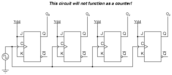
J-K flip-flops are ideally suited for this task, because they have the ability to "toggle" their output state at the command of a clock pulse when both J and K inputs are made "high" (1):

If we consider the two signals (A and B) in this circuit to represent two bits of a binary number, signal A being the LSB and signal B being the MSB, we see that the count sequence is backward: from 11 to 10 to 01 to 00 and back again to 11. Although it might not be counting in the direction we might have assumed, at least it counts!
The following sections explore different types of counter circuits, all made with J-K flip-flops, and all based on the exploitation of that flip-flop's toggle mode of operation.
- REVIEW:
- Binary count sequences follow a pattern of octave frequency division: the frequency of oscillation for each bit, from LSB to MSB, follows a divide-by-two pattern. In other words, the LSB will oscillate at the highest frequency, followed by the next bit at one-half the LSB's frequency, and the next bit at one-half the frequency of the bit before it, etc.
- Circuits may be built that "count" in a binary sequence, using J-K flip-flops set up in the "toggle" mode.
Asynchronous counters
In the previous section, we saw a circuit using one J-K flip-flop that counted backward in a two-bit binary sequence, from 11 to 10 to 01 to 00. Since it would be desirable to have a circuit that could count forward and not just backward, it would be worthwhile to examine a forward count sequence again and look for more patterns that might indicate how to build such a circuit.
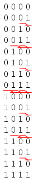
Since we know that binary count sequences follow a pattern of octave (factor of 2) frequency division, and that J-K flip-flop multivibrators set up for the "toggle" mode are capable of performing this type of frequency division, we can envision a circuit made up of several J-K flip-flops, cascaded to produce four bits of output. The main problem facing us is to determine how to connect these flip-flops together so that they toggle at the right times to produce the proper binary sequence. Examine the following binary count sequence, paying attention to patterns preceding the "toggling" of a bit between 0 and 1:
Note that each bit in this four-bit sequence toggles when the bit before it (the bit having a lesser significance, or place-weight), toggles in a particular direction: from 1 to 0. Small arrows indicate those points in the sequence where a bit toggles, the head of the arrow pointing to the previous bit transitioning from a "high" (1) state to a "low" (0) state:

Starting with four J-K flip-flops connected in such a way to always be in the "toggle" mode, we need to determine how to connect the clock inputs in such a way so that each succeeding bit toggles when the bit before it transitions from 1 to 0. The Q outputs of each flip-flop will serve as the respective binary bits of the final, four-bit count:
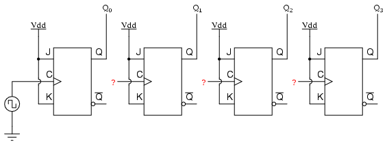
If we used flip-flops with negative-edge triggering (bubble symbols on the clock inputs), we could simply connect the clock input of each flip-flop to the Q output of the flip-flop before it, so that when the bit before it changes from a 1 to a 0, the "falling edge" of that signal would "clock" the next flip-flop to toggle the next bit:

This circuit would yield the following output waveforms, when "clocked" by a repetitive source of pulses from an oscillator:
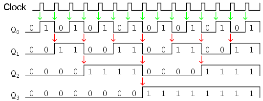
The first flip-flop (the one with the Q0 output), has a positive-edge triggered clock input, so it toggles with each rising edge of the clock signal. Notice how the clock signal in this example has a duty cycle less than 50%. I've shown the signal in this manner for the purpose of demonstrating how the clock signal need not be symmetrical to obtain reliable, "clean" output bits in our four-bit binary sequence. In the very first flip-flop circuit shown in this chapter, I used the clock signal itself as one of the output bits. This is a bad practice in counter design, though, because it necessitates the use of a square wave signal with a 50% duty cycle ("high" time = "low" time) in order to obtain a count sequence where each and every step pauses for the same amount of time. Using one J-K flip-flop for each output bit, however, relieves us of the necessity of having a symmetrical clock signal, allowing the use of practically any variety of high/low waveform to increment the count sequence.
As indicated by all the other arrows in the pulse diagram, each succeeding output bit is toggled by the action of the preceding bit transitioning from "high" (1) to "low" (0). This is the pattern necessary to generate an "up" count sequence.
A less obvious solution for generating an "up" sequence using positive-edge triggered flip-flops is to "clock" each flip-flop using the Q' output of the preceding flip-flop rather than the Q output. Since the Q' output will always be the exact opposite state of the Q output on a J-K flip-flop (no invalid states with this type of flip-flop), a high-to-low transition on the Q output will be accompanied by a low-to-high transition on the Q' output. In other words, each time the Q output of a flip-flop transitions from 1 to 0, the Q' output of the same flip-flop will transition from 0 to 1, providing the positive-going clock pulse we would need to toggle a positive-edge triggered flip-flop at the right moment:

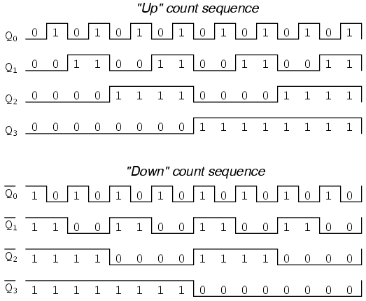
One way we could expand the capabilities of either of these two counter circuits is to regard the Q' outputs as another set of four binary bits. If we examine the pulse diagram for such a circuit, we see that the Q' outputs generate a down-counting sequence, while the Q outputs generate an up-counting sequence:

Unfortunately, all of the counter circuits shown thusfar share a common problem: the ripple effect. This effect is seen in certain types of binary adder and data conversion circuits, and is due to accumulative propagation delays between cascaded gates. When the Q output of a flip-flop transitions from 1 to 0, it commands the next flip-flop to toggle. If the next flip-flop toggle is a transition from 1 to 0, it will command the flip-flop after it to toggle as well, and so on. However, since there is always some small amount of propagation delay between the command to toggle (the clock pulse) and the actual toggle response (Q and Q' outputs changing states), any subsequent flip-flops to be toggled will toggle some time after the first flip-flop has toggled. Thus, when multiple bits toggle in a binary count sequence, they will not all toggle at exactly the same time:

As you can see, the more bits that toggle with a given clock pulse, the more severe the accumulated delay time from LSB to MSB. When a clock pulse occurs at such a transition point (say, on the transition from 0111 to 1000), the output bits will "ripple" in sequence from LSB to MSB, as each succeeding bit toggles and commands the next bit to toggle as well, with a small amount of propagation delay between each bit toggle. If we take a close-up look at this effect during the transition from 0111 to 1000, we can see that there will be false output counts generated in the brief time period that the "ripple" effect takes place:
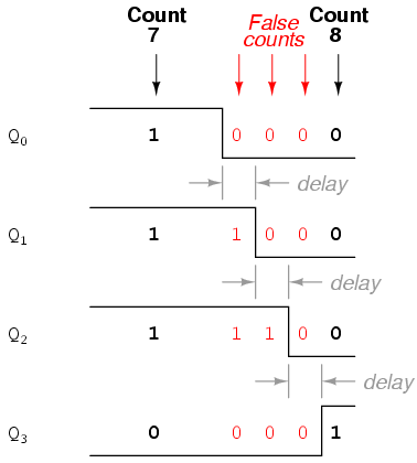
Instead of cleanly transitioning from a "0111" output to a "1000" output, the counter circuit will very quickly ripple from 0111 to 0110 to 0100 to 0000 to 1000, or from 7 to 6 to 4 to 0 and then to 8. This behavior earns the counter circuit the name of ripple counter, or asynchronous counter.
In many applications, this effect is tolerable, since the ripple happens very, very quickly (the width of the delays has been exaggerated here as an aid to understanding the effects). If all we wanted to do was drive a set of light-emitting diodes (LEDs) with the counter's outputs, for example, this brief ripple would be of no consequence at all. However, if we wished to use this counter to drive the "select" inputs of a multiplexer, index a memory pointer in a microprocessor (computer) circuit, or perform some other task where false outputs could cause spurious errors, it would not be acceptable. There is a way to use this type of counter circuit in applications sensitive to false, ripple-generated outputs, and it involves a principle known as strobing.
Most decoder and multiplexer circuits are equipped with at least one input called the "enable." The output(s) of such a circuit will be active only when the enable input is made active. We can use this enable input to strobe the circuit receiving the ripple counter's output so that it is disabled (and thus not responding to the counter output) during the brief period of time in which the counter outputs might be rippling, and enabled only when sufficient time has passed since the last clock pulse that all rippling will have ceased. In most cases, the strobing signal can be the same clock pulse that drives the counter circuit:

With an active-low Enable input, the receiving circuit will respond to the binary count of the four-bit counter circuit only when the clock signal is "low." As soon as the clock pulse goes "high," the receiving circuit stops responding to the counter circuit's output. Since the counter circuit is positive-edge triggered (as determined by the first flip-flop clock input), all the counting action takes place on the low-to-high transition of the clock signal, meaning that the receiving circuit will become disabled just before any toggling occurs on the counter circuit's four output bits. The receiving circuit will not become enabled until the clock signal returns to a low state, which should be a long enough time after all rippling has ceased to be "safe" to allow the new count to have effect on the receiving circuit. The crucial parameter here is the clock signal's "high" time: it must be at least as long as the maximum expected ripple period of the counter circuit. If not, the clock signal will prematurely enable the receiving circuit, while some rippling is still taking place.
Another disadvantage of the asynchronous, or ripple, counter circuit is limited speed. While all gate circuits are limited in terms of maximum signal frequency, the design of asynchronous counter circuits compounds this problem by making propagation delays additive. Thus, even if strobing is used in the receiving circuit, an asynchronous counter circuit cannot be clocked at any frequency higher than that which allows the greatest possible accumulated propagation delay to elapse well before the next pulse.
The solution to this problem is a counter circuit that avoids ripple altogether. Such a counter circuit would eliminate the need to design a "strobing" feature into whatever digital circuits use the counter output as an input, and would also enjoy a much greater operating speed than its asynchronous equivalent. This design of counter circuit is the subject of the next section.
- REVIEW:
- An "up" counter may be made by connecting the clock inputs of positive-edge triggered J-K flip-flops to the Q' outputs of the preceding flip-flops. Another way is to use negative-edge triggered flip-flops, connecting the clock inputs to the Q outputs of the preceding flip-flops. In either case, the J and K inputs of all flip-flops are connected to Vcc or Vdd so as to always be "high."
- Counter circuits made from cascaded J-K flip-flops where each clock input receives its pulses from the output of the previous flip-flop invariably exhibit a ripple effect, where false output counts are generated between some steps of the count sequence. These types of counter circuits are called asynchronous counters, or ripple counters.
- Strobing is a technique applied to circuits receiving the output of an asynchronous (ripple) counter, so that the false counts generated during the ripple time will have no ill effect. Essentially, the enable input of such a circuit is connected to the counter's clock pulse in such a way that it is enabled only when the counter outputs are not changing, and will be disabled during those periods of changing counter outputs where ripple occurs.
Synchronous counters
A synchronous counter, in contrast to an asynchronous counter, is one whose output bits change state simultaneously, with no ripple. The only way we can build such a counter circuit from J-K flip-flops is to connect all the clock inputs together, so that each and every flip-flop receives the exact same clock pulse at the exact same time:

Now, the question is, what do we do with the J and K inputs? We know that we still have to maintain the same divide-by-two frequency pattern in order to count in a binary sequence, and that this pattern is best achieved utilizing the "toggle" mode of the flip-flop, so the fact that the J and K inputs must both be (at times) "high" is clear. However, if we simply connect all the J and K inputs to the positive rail of the power supply as we did in the asynchronous circuit, this would clearly not work because all the flip-flops would toggle at the same time: with each and every clock pulse!
Let's examine the four-bit binary counting sequence again, and see if there are any other patterns that predict the toggling of a bit. Asynchronous counter circuit design is based on the fact that each bit toggle happens at the same time that the preceding bit toggles from a "high" to a "low" (from 1 to 0). Since we cannot clock the toggling of a bit based on the toggling of a previous bit in a synchronous counter circuit (to do so would create a ripple effect) we must find some other pattern in the counting sequence that can be used to trigger a bit toggle:
Examining the four-bit binary count sequence, another predictive pattern can be seen. Notice that just before a bit toggles, all preceding bits are "high:"

This pattern is also something we can exploit in designing a counter circuit. If we enable each J-K flip-flop to toggle based on whether or not all preceding flip-flop outputs (Q) are "high," we can obtain the same counting sequence as the asynchronous circuit without the ripple effect, since each flip-flop in this circuit will be clocked at exactly the same time:
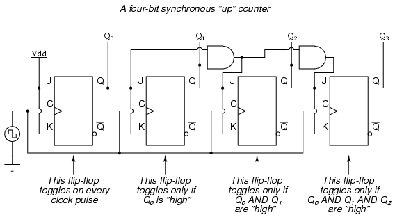
The result is a four-bit synchronous "up" counter. Each of the higher-order flip-flops are made ready to toggle (both J and K inputs "high") if the Q outputs of all previous flip-flops are "high." Otherwise, the J and K inputs for that flip-flop will both be "low," placing it into the "latch" mode where it will maintain its present output state at the next clock pulse. Since the first (LSB) flip-flop needs to toggle at every clock pulse, its J and K inputs are connected to Vcc or Vdd, where they will be "high" all the time. The next flip-flop need only "recognize" that the first flip-flop's Q output is high to be made ready to toggle, so no AND gate is needed. However, the remaining flip-flops should be made ready to toggle only when all lower-order output bits are "high," thus the need for AND gates.
To make a synchronous "down" counter, we need to build the circuit to recognize the appropriate bit patterns predicting each toggle state while counting down. Not surprisingly, when we examine the four-bit binary count sequence, we see that all preceding bits are "low" prior to a toggle (following the sequence from bottom to top):
Since each J-K flip-flop comes equipped with a Q' output as well as a Q output, we can use the Q' outputs to enable the toggle mode on each succeeding flip-flop, being that each Q' will be "high" every time that the respective Q is "low:"

Taking this idea one step further, we can build a counter circuit with selectable between "up" and "down" count modes by having dual lines of AND gates detecting the appropriate bit conditions for an "up" and a "down" counting sequence, respectively, then use OR gates to combine the AND gate outputs to the J and K inputs of each succeeding flip-flop:

This circuit isn't as complex as it might first appear. The Up/Down control input line simply enables either the upper string or lower string of AND gates to pass the Q/Q' outputs to the succeeding stages of flip-flops. If the Up/Down control line is "high," the top AND gates become enabled, and the circuit functions exactly the same as the first ("up") synchronous counter circuit shown in this section. If the Up/Down control line is made "low," the bottom AND gates become enabled, and the circuit functions identically to the second ("down" counter) circuit shown in this section.
To illustrate, here is a diagram showing the circuit in the "up" counting mode (all disabled circuitry shown in grey rather than black):

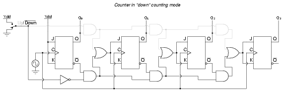
Here, shown in the "down" counting mode, with the same grey coloring representing disabled circuitry:
Up/down counter circuits are very useful devices. A common application is in machine motion control, where devices called rotary shaft encoders convert mechanical rotation into a series of electrical pulses, these pulses "clocking" a counter circuit to track total motion:

As the machine moves, it turns the encoder shaft, making and breaking the light beam between LED and phototransistor, thereby generating clock pulses to increment the counter circuit. Thus, the counter integrates, or accumulates, total motion of the shaft, serving as an electronic indication of how far the machine has moved. If all we care about is tracking total motion, and do not care to account for changes in the direction of motion, this arrangement will suffice. However, if we wish the counter to increment with one direction of motion and decrement with the reverse direction of motion, we must use an up/down counter, and an encoder/decoding circuit having the ability to discriminate between different directions.
If we re-design the encoder to have two sets of LED/phototransistor pairs, those pairs aligned such that their square-wave output signals are 90o out of phase with each other, we have what is known as a quadrature output encoder (the word "quadrature" simply refers to a 90o angular separation). A phase detection circuit may be made from a D-type flip-flop, to distinguish a clockwise pulse sequence from a counter-clockwise pulse sequence:

When the encoder rotates clockwise, the "D" input signal square-wave will lead the "C" input square-wave, meaning that the "D" input will already be "high" when the "C" transitions from "low" to "high," thus setting the D-type flip-flop (making the Q output "high") with every clock pulse. A "high" Q output places the counter into the "Up" count mode, and any clock pulses received by the clock from the encoder (from either LED) will increment it. Conversely, when the encoder reverses rotation, the "D" input will lag behind the "C" input waveform, meaning that it will be "low" when the "C" waveform transitions from "low" to "high," forcing the D-type flip-flop into the reset state (making the Q output "low") with every clock pulse. This "low" signal commands the counter circuit to decrement with every clock pulse from the encoder.
This circuit, or something very much like it, is at the heart of every position-measuring circuit based on a pulse encoder sensor. Such applications are very common in robotics, CNC machine tool control, and other applications involving the measurement of reversible, mechanical motion.
Counter modulus
Lessons In Electric Circuits copyright (C) 2000-2006 Tony R. Kuphaldt, under the terms and conditions of the Design Science License.
PreviousContentsNext